Project Adrift - technical description and build photos
Space debris consists of bits of man-made scrap in orbit around the Earth - old satellites, parts of rockets and so on. The trajectories of many of the larger pieces are recorded in a database, updated daily, from which current positions can be extrapolated. A helpful resource to avoid collisions when launching a rocket.
Nick, Dan and Sean created a system that looked at the debris passing through a 600Km window over the UK, displayed various details, and also sent MIDI data to trigger the phonograph machine I made. To cover 1000 pre-recorded stereo tracks, the machine had 8 carriage systems, each allowing a stylus to be accurately placed on one of 125 loops. As MIDI velocity data consists of 128 values, 1 to 125 could be used to set the loop, with 0 returning the carriage to the home position. Each carriage was assigned a note, so D3 with velocity of 112 would send carriage no. 3 to loop no. 112 until the note was released.
The loops were arranged low to high frequency from left to right, with larger pieces of debris triggering sounds containing more bass.
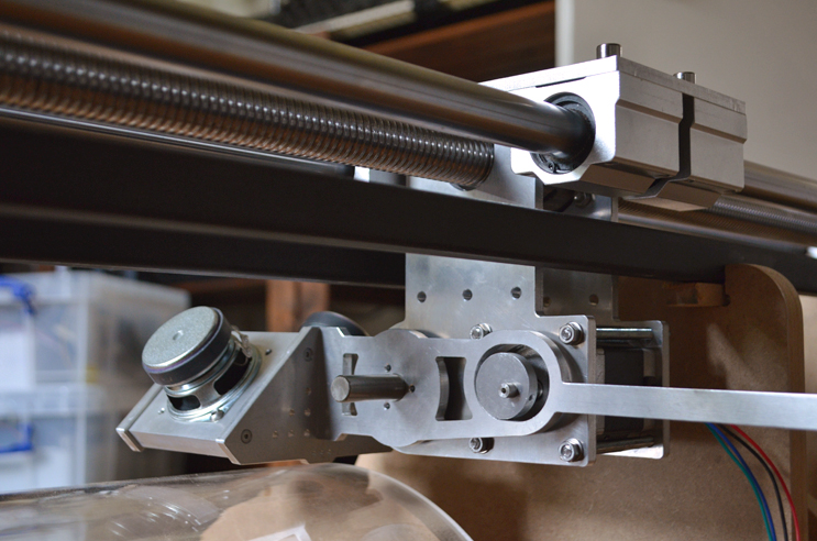
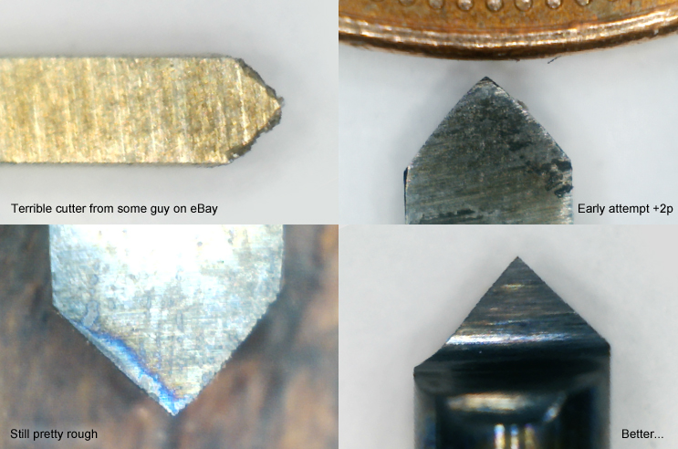
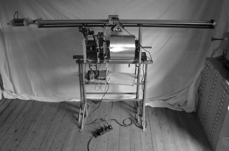
To record onto the cylinder a rig was built consisting of a 2.2m ballscrew, sliding carriage, pivoting arm and recording head. This was a major part of the project, particularly the development of the recording head. Early tests were pretty bad - it took a few versions to improve the audio quality.
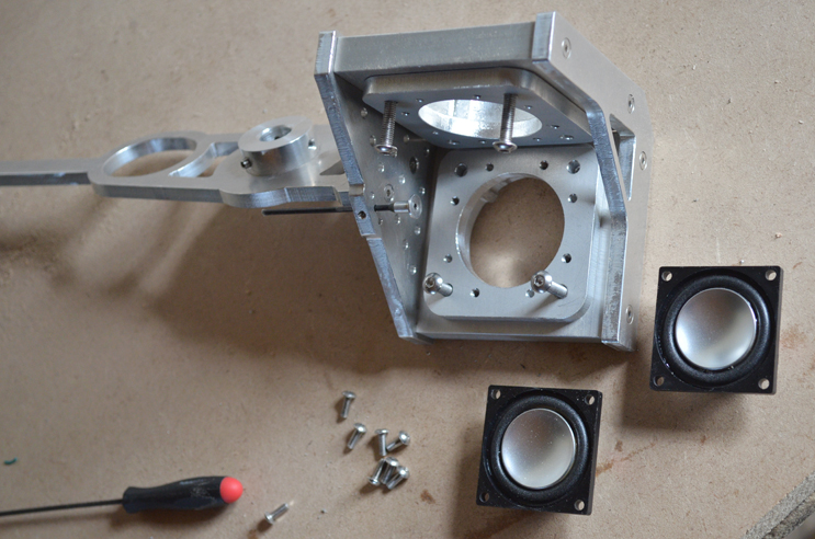
Version one had relatively bulky speakers to move the cutter, as well as brass supports and a fibreglass support rod, all of which were way too heavy.
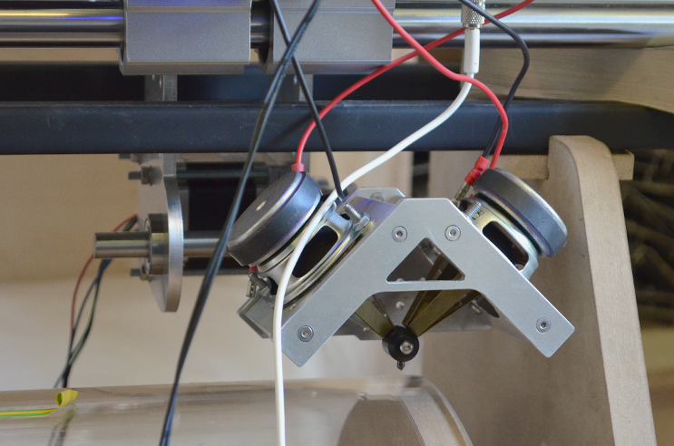
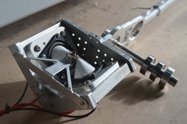
An eccentric cam was used to lift the pivoting record head up and down. This had to be timed so that the cutter made contact with the cylinder exactly as the audio started, and then lifted after exactly one revolution of the cylinder.
At the time of building I was reading Pierre Schaeffer's "In Search of a Concrete Music", and he coincidentally describes pretty much the same process whilst making locked groove records in 1948, mentioning the disc cutter operator "...skilfully raising the cutter once the groove has 'bitten its tail', he has isolated a 'sound fragment' that has neither beginning nor end, a sliver of sound isolated from any temporal context..."
Sean made a MAX patch for me that synched the playback of the audio files by sending a signal to the motor setup. I just had to press the space bar on my laptop and the cutter would descend, cut the loop with the audio timed correctly, lift again, advance horizontally 1.4mm, and load the next audio file automatically.
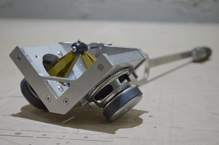
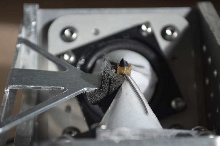
The recording head was re-made with smaller speakers, paper cones, and a lighter cutter assembly.
Further revisions, then the final version below. A microscope was used to help grind the cutter. Further improvements could have been made, but the project had an impending deadline...
Originally the plan was to record the audio onto an extruded acrylic tube, but the diameter of the section bought for testing was way too wobbly.
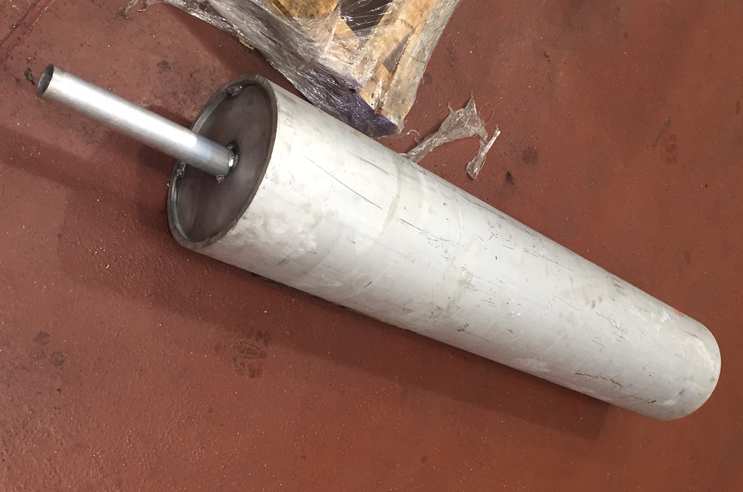
After a few enquiries GWF Engineering said they could source a suitable aluminium tube, fix a 2 inch shaft through the centre, and machine the circumference. They seemed genuinely interested in the project, and had lathes big enough for the job as they also make immense butterfly valves for hydroelectric power stations. They sent the 1.5m cylinder, and also a shorter section for testing.
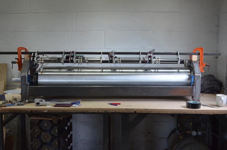
Recording onto aluminium seemed possible if the metal was lacquered first, but there was some doubt as to how long the lacquer would last before playback deteriorated. Recording directly into the aluminium seemed worth trying - the rig below had to be built in its entirety to prove the principle.
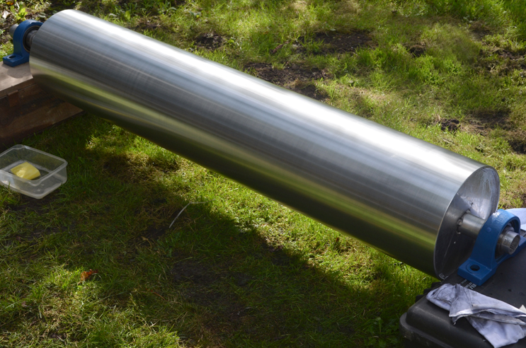
The main cylinder before machining
After machining
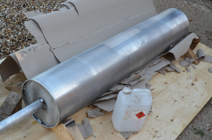
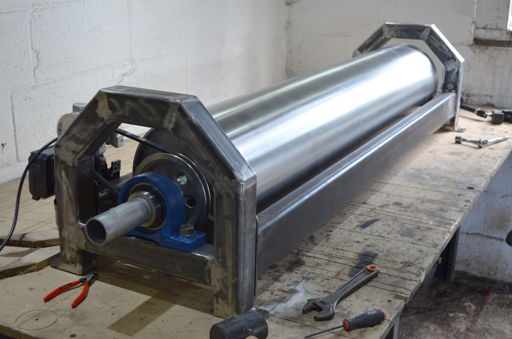
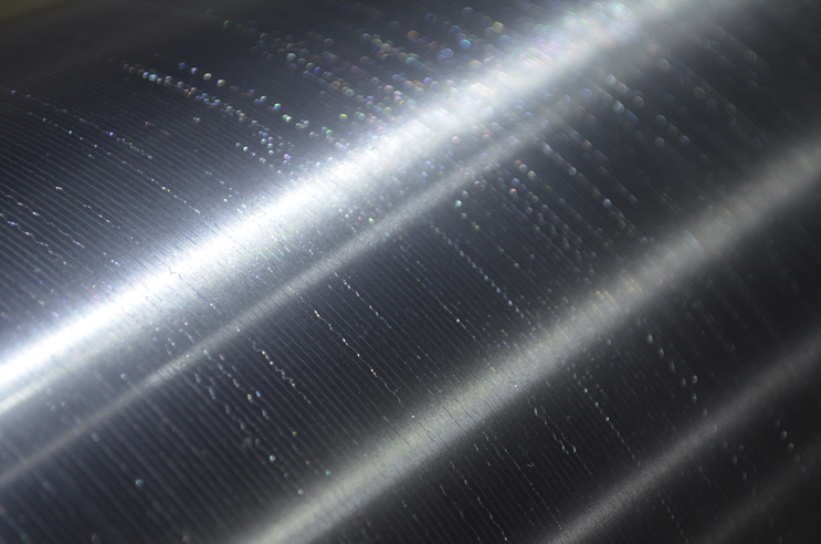
After cleaning
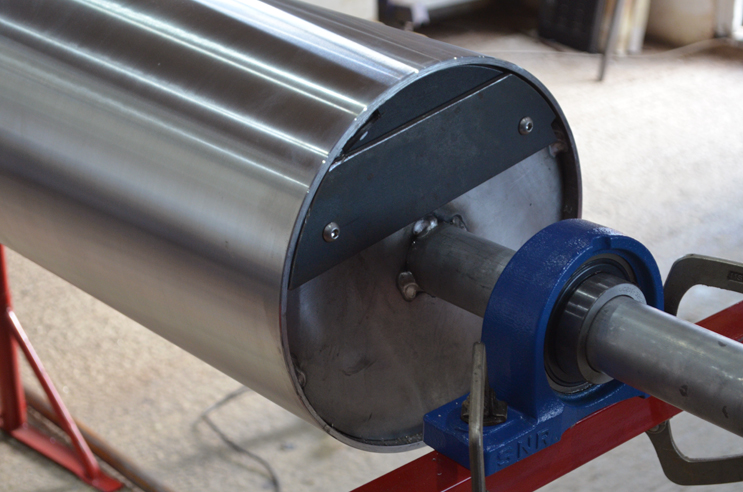
The circumference of the cylinder was machined with reference to the shaft welded in place along the centre, but as the shaft was slightly off-centre from the initial section of tubing (due to 1mm or so tolerance around the end caps), the cylinder needed balancing. After drilling a hole in one of the end caps, fitting a 1" tube and stuffing it with material to fine tune looked less likely as GWF Engineering had been thorough enough to cement further bracing along the tube to prevent any deflection during the machining process. Steel plates were added to balance, and did the job just fine.
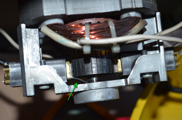
Adding weights to balance the cylinder was one of those unexpected "takes half a day" tasks that can be entirely expected on any complex project. Another example of this involved turning on the vacuum bed on the CNC router to hear spluttering and high voltage sparks, only to finally discover, an hour later, that one motor brush has worn in a fantastically bizarre way that has created a brittle conductive protrusion that is shorting against the frame of the motor.
It's difficult to allow for stuff like this when quoting for a job, although I usually add 2% in case bees steal my spanners.
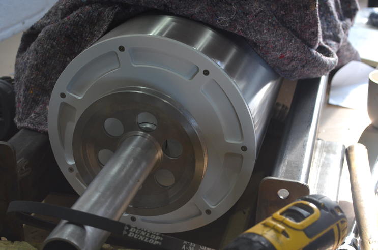
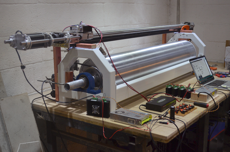
Pulley fitted and some end caps to hide the weights etc.
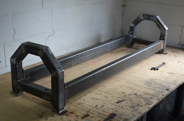
Hefty steel frame to hold the cylinder. The welds had to be nice, as they would be prominently displayed and sprayed gloss white.
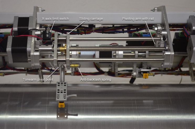
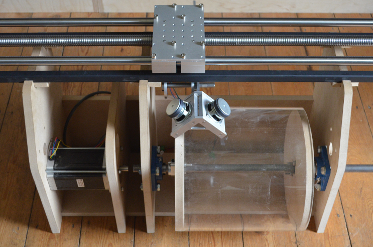
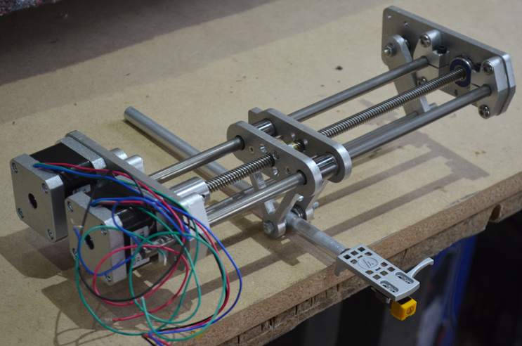
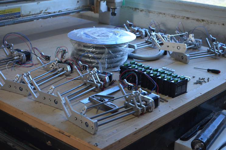
Prototype carriage
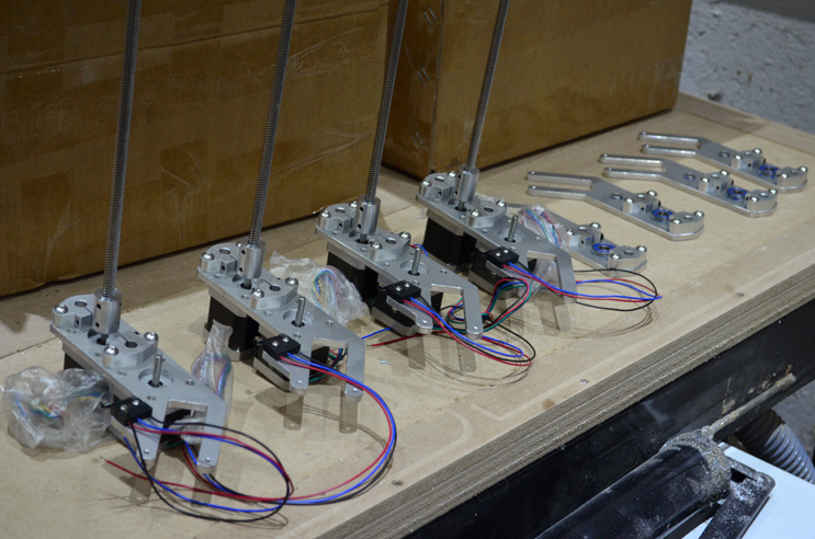
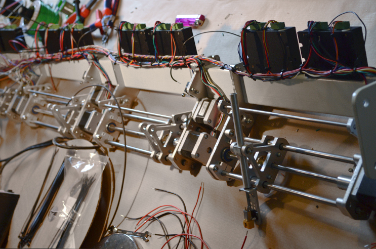
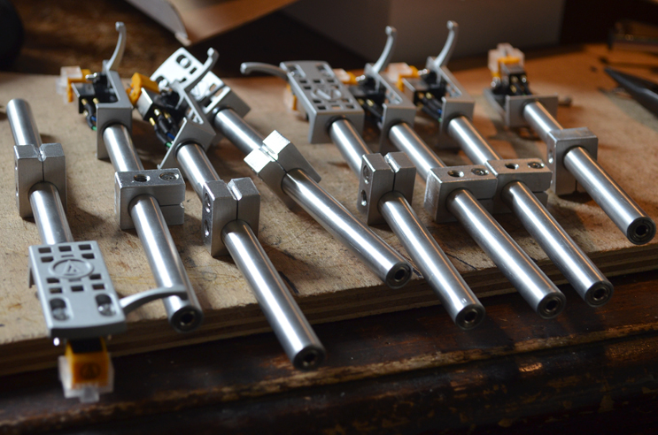
Final carriages being assembled.
Each carriage moved on rails, driven by a trapezoidal leadscrew. The tonearm and stylus fixed to the carriage could be lowered and raised via a pivoting rail mounted on two arms. A limit switch allowed home position feedback on each axis, with the rail switch being additionally connected to the 'enable' input on the carriage's stepper motor driver. This meant that as soon as the stylus begins to descend, the carriage movement is disabled, meaning the system is hard wired to never scrape the needle horizontally along the cylinder.
Whilst calculating the number of pulses needed for the stepper motor to advance the carriage to the next audio loop, it seemed to be out by a factor of four. I then realised the leadscrews have four starting points, so travel 8mm per rotation even though the screw has a 2mm pitch.
Wiring everything took a few days, but was a nice task.
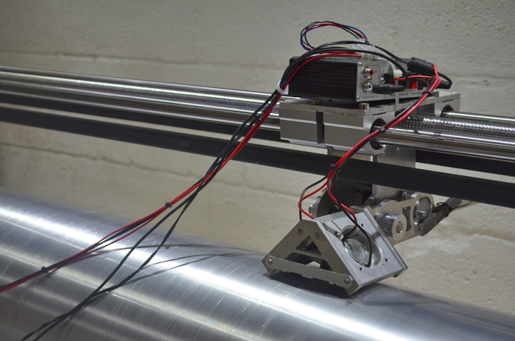
After a lot of preparation, the recording rig was clamped in place above the rather precious cylinder, ready to record 1000 tracks without error.
The cylinder rotated at approximately 16rpm, allowing audio loops of about 3.75 seconds.
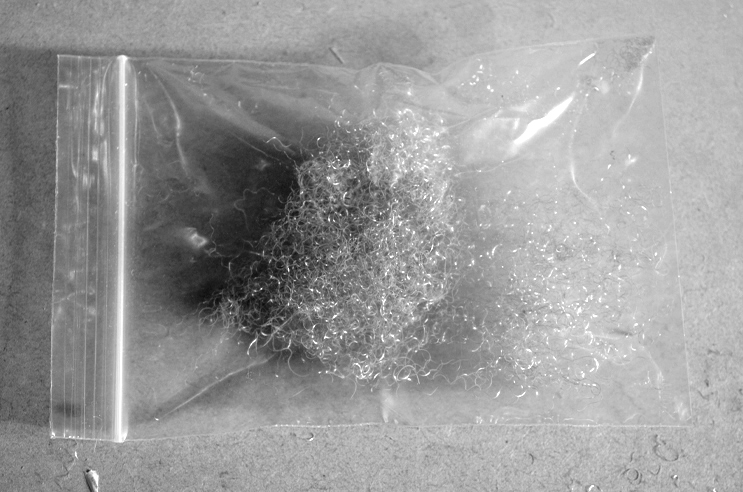
Bag of "anti-sound"
Tonearms with mini jack sockets in the rear. Had there been more time, it would have been better to build a slip ring into the pivot point, so that the trailing audio cables didn't affect the balance of the tonearms. It worked okay anyway after fitting some thin cables.
The headshells and cartridges were supplied by Audio-Technica, who were great sponsors and kindly provided a big box of styli.
This was a really nice project - good to get a chance to get stuck into something relatively complex. It also gave me a huge new respect for the quality of commercial vinyl records.
During one of the more intense phases I went for a country walk and found myself looking out over a freshly ploughed field. Gazing across the furrowed plateau, I had a sudden vision that I was a tiny piece of dust sat amongst the grooves of a vast brown record. Best to get back to the workshop and stay away from that fresh air.
During the press conference at the Royal Astronomical Society I was interested to hear the term "physical engineer", a retronym to differentiate from software engineer I suppose. Or ghost engineer.
Handy tip: If you have a bunch of Arduinos all receiving the same MIDI signal, you only need one optocoupler - the buffered output of the optocoupler is enough to connect to all of them, as the Arduino serial RX draws negligible current.